Learning my ventilation’s secret language
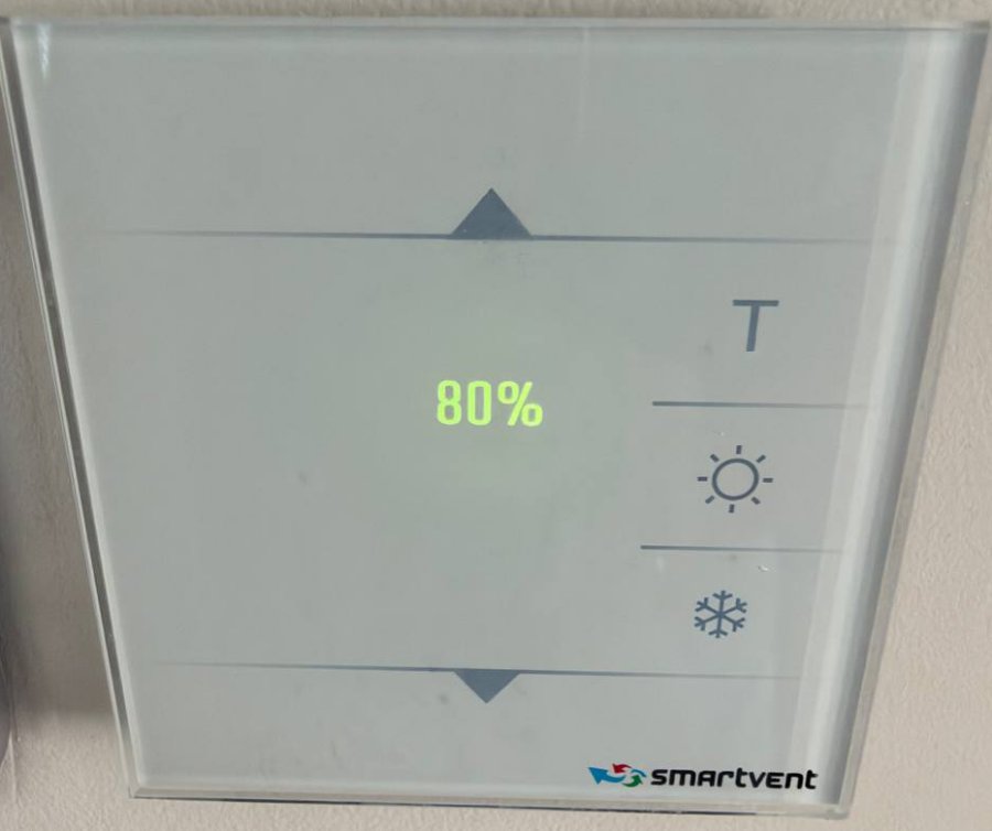
This panel on my wall was the only way to control the ventilation in my house. It has arrows for the fan speed, a T button for modes, a sun and a snowflake. There used to be an app too. But the small company that made the app module went bankrupt, and the app went with it.
My house has a heat recovery ventilator, an HRV. It’s a box in the garage that pulls fresh air in and stale air out all day and all night. On the way through, the warm air going out heats the cold air coming in, so you don’t throw your heating out of the window. Mine is a Smartvent Ecobox, made in Poland. It’s a good box, it just doesn’t talk to anything else.
Now it talks to Home Assistant, the open-source system that runs my house. Home Assistant sees the speed and the mode, can change them, and turns the fan up and down by itself from the CO2 in the rooms. The panel on the wall still works, exactly as before.
This is the second half of a weekend. On Friday evening and Saturday morning, Claude and I taught Home Assistant to read my water meter. I wrote about that in Reading a water meter I’m not allowed to touch. It went so well that I didn’t want to stop. So on Sunday at 13:13 I gave Claude the next job: the ventilation.
At 22:48 the same evening Home Assistant changed the fan speed for the first time. On Monday at 08:27 the fan was running on CO2. That’s about eight hours of work, without the breaks and the night. In those hours we decoded a protocol nobody had published, tested it from my laptop, set up a Wi-Fi adapter without soldering anything, and wrote the Home Assistant part. So that was two projects in one weekend, and I still find that a bit crazy.
If you read the water meter post, you know the picture. If you didn’t: in Iron Man, Tony Stark says what he wants, and JARVIS, his AI, does the research and the calculations. That’s how this weekend felt. Claude, the AI from Anthropic, was my JARVIS. On Friday and Saturday the suit helped me design and print a camera holder. On Sunday there was nothing to print. It was all cables, a multimeter and a language nobody had written down.
So who did what? Same as on Saturday: I said what I wanted and made the decisions. I took photos, measured with a multimeter, plugged in the cables, pressed every button on the panel and set up the Wi-Fi adapter. Claude read the manual, decoded the protocol, wrote the code and configured Home Assistant. It worked as an agent: it had access to my home-automation repository, a command line on a small server, Home Assistant, and, over SSH, my laptop with a USB adapter plugged into the HRV.
Here is the second half of the weekend in one table:
| When | What happened |
|---|---|
| Sun 13:13 | I send the manual and photos of the board: “it’s clearly possible somehow” |
| Sun 13:36 | Claude decodes my old recordings of the panel cable. One checkbox was missing |
| Sun 17:18 | I ask: what if we just use the second socket? |
| Sun 20:07 | my multimeter numbers show the cable is RS-485, not what Claude thought |
| Sun 20:57 | from my laptop, the HRV takes our first command: 40 %, then back to 80 % |
| Sun 22:48 | a small Wi-Fi adapter is on the socket, and Home Assistant sets 60 % |
| Mon 08:05 | we measure how much power each fan speed uses |
| Mon 08:27 | the fan runs on CO2 |
Not everything went well, though. Claude was wrong about the wiring for a whole afternoon, and the energy saving is much smaller than we planned. I left all of that in.
The short version
- The problem. The HRV has no app, no Wi-Fi and no published protocol. Only a panel on the wall, connected by a network cable.
- What works. The panel talks to the HRV over a simple serial bus (RS-485). The HRV has a second socket for that bus that nobody was using. A small Elfin EW11A adapter sits on that socket and passes every byte to Home Assistant over Wi-Fi.
- The trick. Once a second the HRV asks “does anybody want to write?”, and the panel never answers. So Home Assistant answers in that gap, and checks the next status message to see if it worked.
- The result. Home Assistant sets the fan from the CO2 in the rooms and boosts it for a shower. But my house rarely gets to the slow speed, so it saves about a sixth of the fan’s power, not the two thirds we hoped for.
Here is the real data from the first day and a half, from the moment the automation went on:
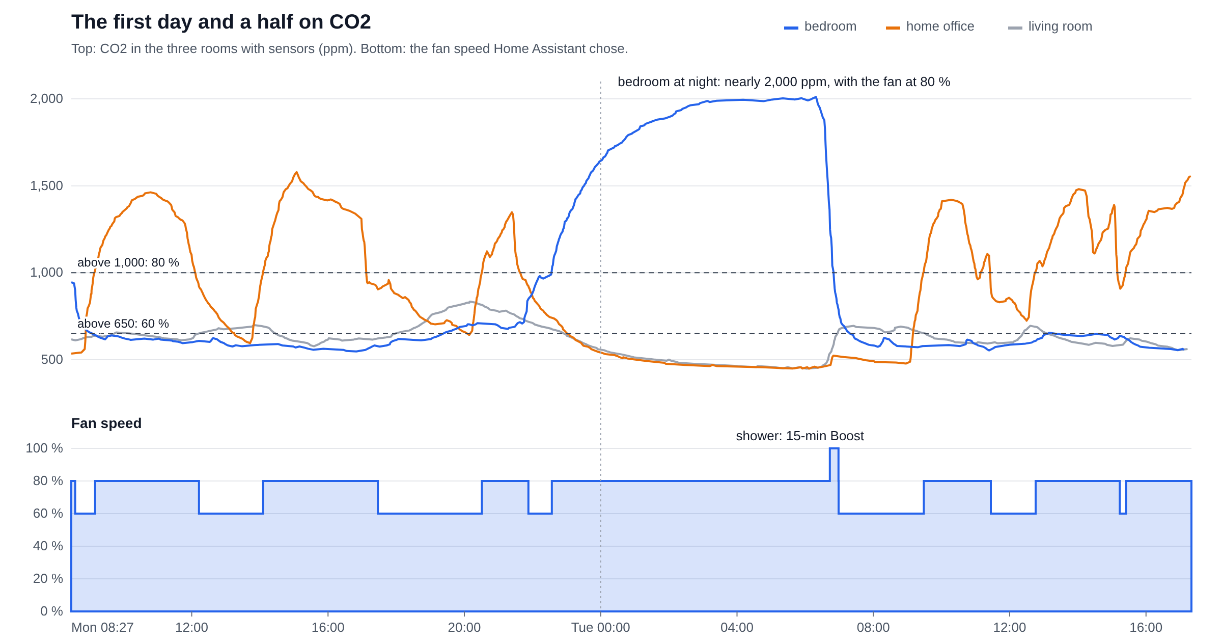
Some of it is exactly what I wanted. The fan follows the rooms. On Tuesday morning someone took a shower at 06:43, the bathroom humidity jumped from 40 to 64 %, and the HRV went to Boost for 15 minutes and then came back down by itself. I didn’t touch anything.
But look at the bottom of the chart. The fan never went down to 40 %. In the daytime the home office goes over 1,000 ppm whenever someone works there, and the rest of the time something in the house is still above 650. So it switches between 60 % and 80 %.
So the saving is smaller than the plan. The 24 hours before the automation used 2.34 kWh. The first 24 hours with it used 1.93 kWh, even with a Boost in it. That’s about 0.4 kWh a day, roughly a sixth. Claude’s plan had said about 1.5 kWh a day. It’s not nothing, and the house gets more air when it needs it. But I was hoping for more, and I’m a little disappointed.
The bedroom is a different story. On the first night it went up to nearly 2,000 ppm with the fan at 80 %. Claude had warned me about that before we started: a faster fan doesn’t fix a room the air doesn’t reach. That one is a job for me, a screwdriver and the bedroom vent, not for software.
If some of these names are new to you:
| Name | What it is |
|---|---|
| HRV | heat recovery ventilator: fresh air in, stale air out, the heat stays in the house |
| RS-485 | a simple, old way to send serial data over a twisted pair of wires; used in a lot of industrial equipment |
| Elfin EW11A | a small box (about the size of a USB stick) that connects an RS-485 bus to Wi-Fi |
| MQTT | a simple way for devices to send messages; Home Assistant uses it a lot |
| logic analyzer | a cheap USB gadget that records what happens on a few wires, so you can look at it later |
The panel, the board and a dead app
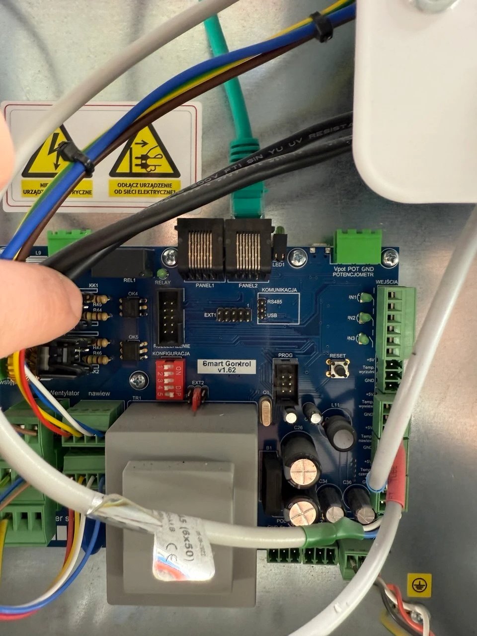
On Sunday at 13:13 I sent Claude the HRV manual (a PDF in Polish), a photo of the panel and photos of the board inside the box. My message was:
right now I have no way to control the HRV through HA. but clearly it can be done somehow. […] the company that did the remote control went bankrupt. do deep research and propose what I can do myself - build - buy.
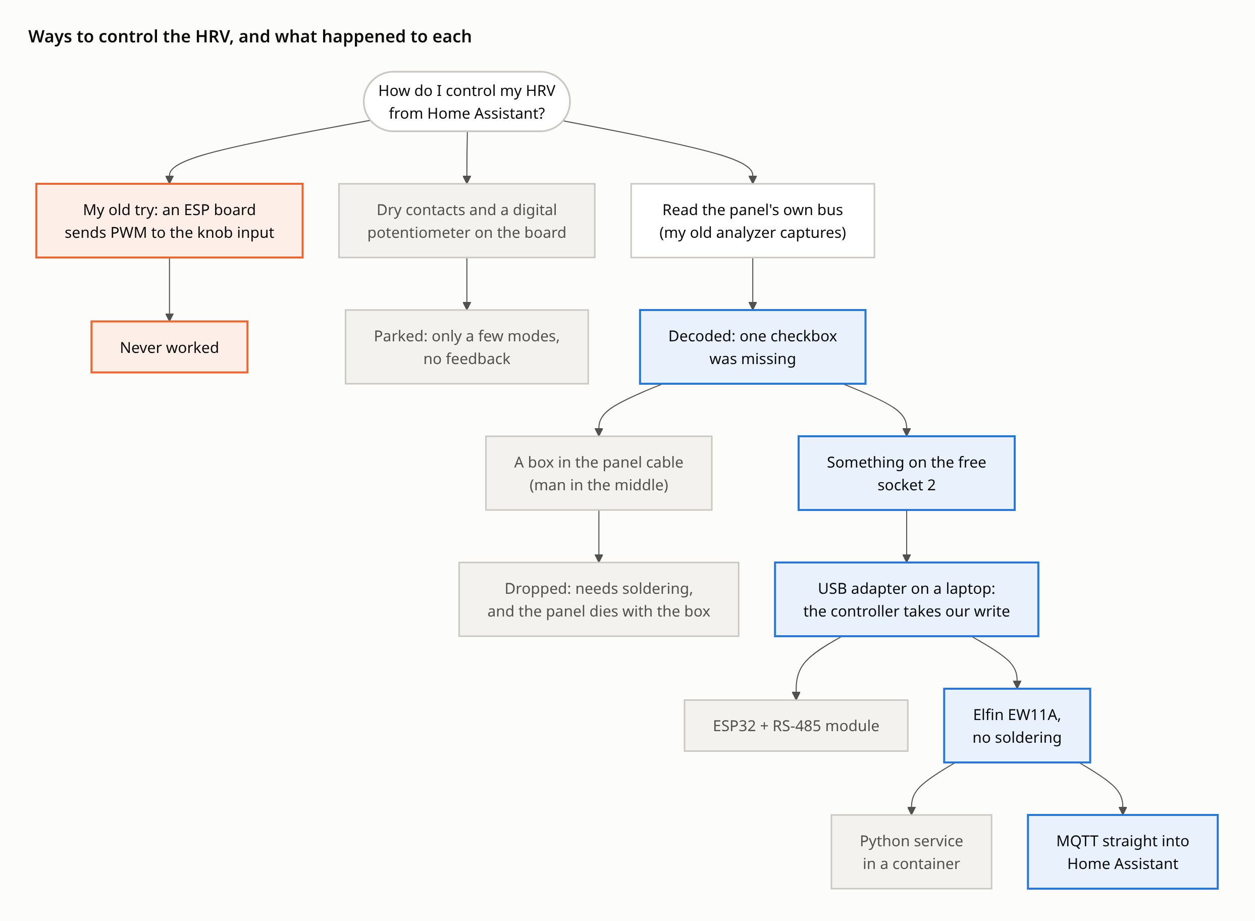
Claude read the manual and found three official ways in. There are three “dry contact” inputs: close one and you get Boost, or extract only, or Sleep. There is an input for an external speed knob. And there are the two network sockets for the panel, marked PANEL1 and PANEL2. The manual says nothing about what goes over them.
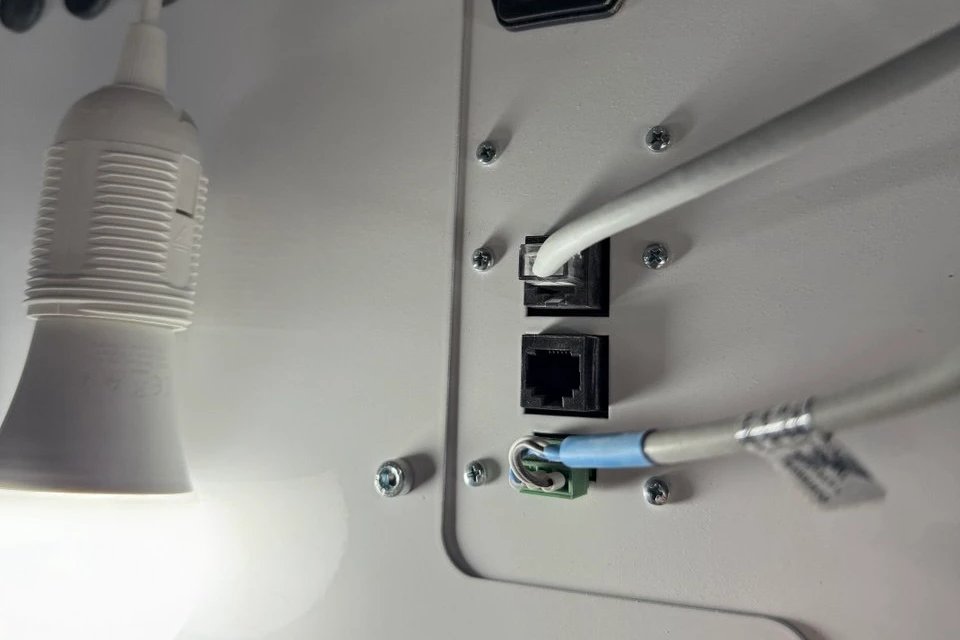
The panel cable goes into the top socket. The bottom one was empty. Claude guessed that the bankrupt company’s Wi-Fi module used to sit there.
Claude’s first plan was an ESP32 board with relays on the three inputs and a digital potentiometer pretending to be the speed knob. It would work, but you would only get a few modes and no feedback. Talking to the panel’s own cable would give you everything, but “you’ll have to work out the protocol yourself”.
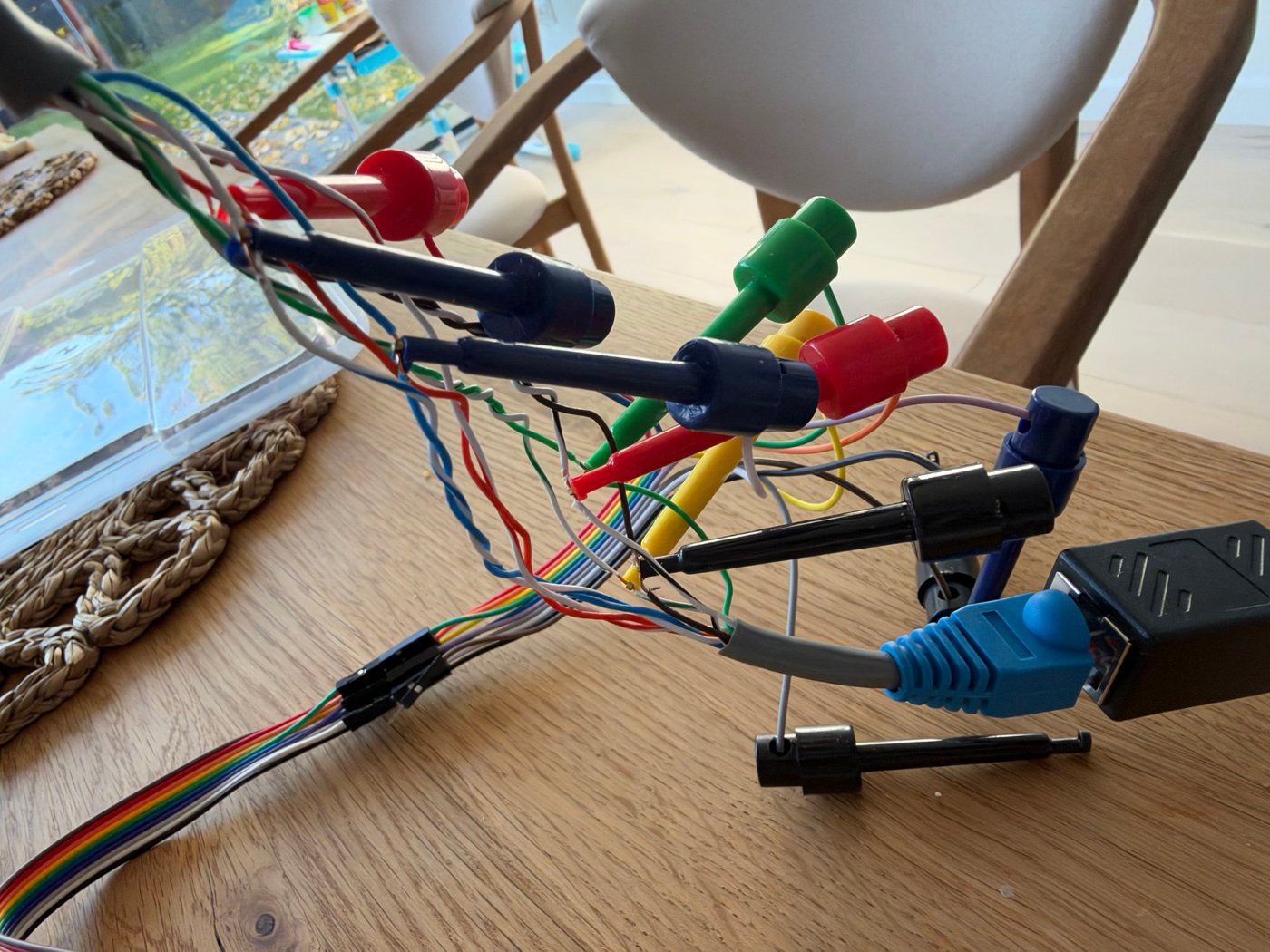
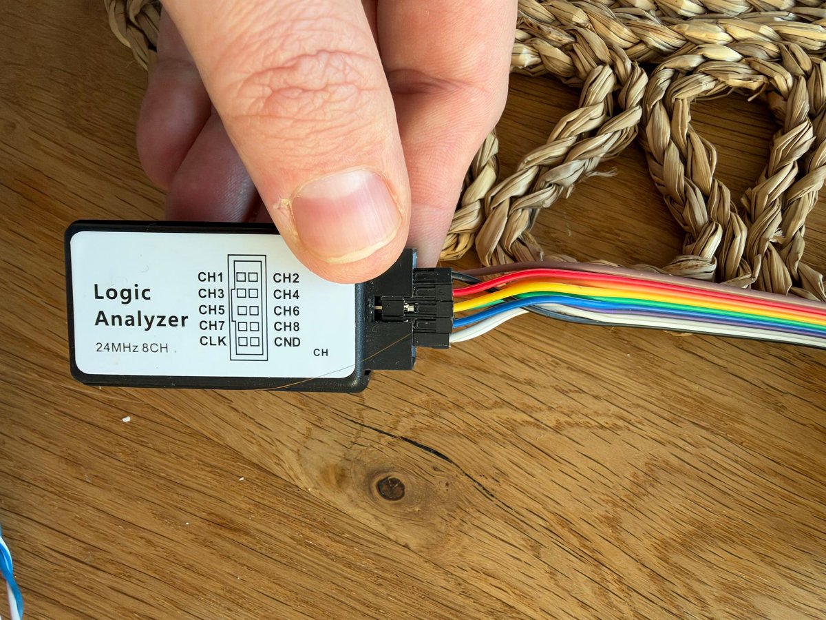
I had tried that before. A while ago I had recorded the panel cable with a cheap logic analyzer, and I’d also tried an ESP board on the knob input, but neither went anywhere. The ESP had been sitting in Home Assistant as a dead fan entity ever since. So I sent Claude my old recordings:
panel protocol is the way. I tried to do something like this. not sure it’s correct. but here’s what I have - attached. analyze it
My recordings were right. One checkbox was wrong
Seven minutes later Claude came back with:
Your captures were done right, one checkbox in the decoder was missing.
In the recording software I had told it to read the data at 9600 baud, which was right. But the line is inverted: it sits low and the bits are pulses up. I hadn’t ticked “invert”. With that one box ticked, 1358 bytes came out with zero errors. That was a little painful to read, but it was also a big relief.
Here are the first 70 ms of one cycle in PulseView, with “invert” ticked:
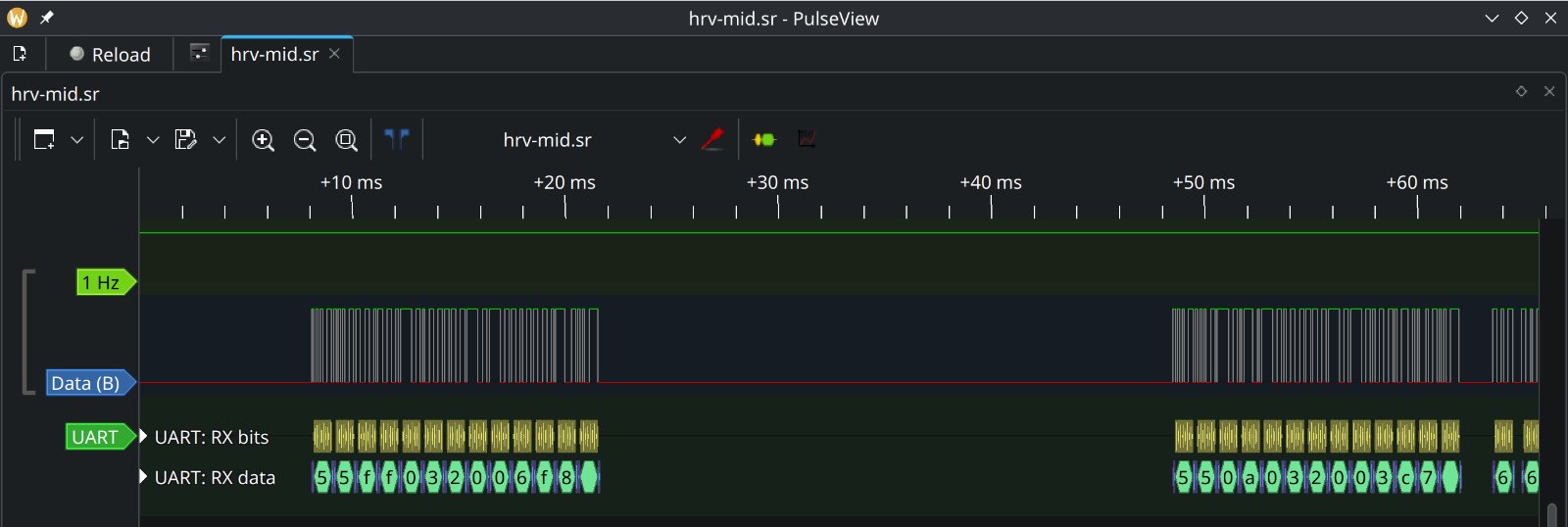
On the left the controller says 55ff032006f8 to everyone. Then nothing happens for about 27 ms. Then it asks the panel, 550a032003c7, and on the right the panel starts its answer with 66. That quiet stretch in the middle comes back later in this story.
And zoomed in on the panel’s answer:
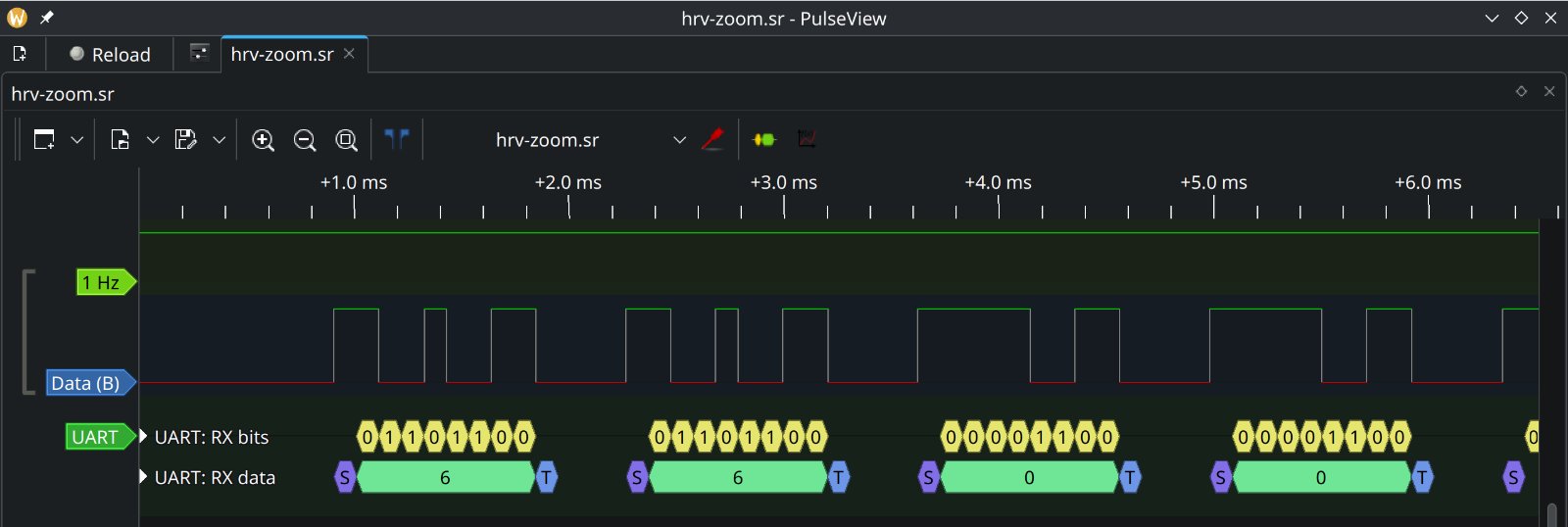
Every character is a start bit (S), eight data bits, lowest first, and a stop bit (T). The first four read 6, 6, 0, 0: the start of 660005132E2800B5, which means “panel to controller: write register 2E, fan to 40 %”.
The protocol turned out to be friendly. Every message is plain text: hex digits followed by a carriage return. The HRV controller writes in lower case, the panel in upper case. Each message has a sender, a receiver, a length, a command, some data and a checksum. Claude found which checksum it was (CRC-8/MAXIM, the one from Dallas 1-Wire sensors) by trying it on every message in my recordings, and it fitted all 15 kinds.
And the conversation goes like this. Once a second the controller sends a message to everyone (a “broadcast”), then asks the panel if it has anything to say. The panel says “nothing”, or “send me the status”, or “set the fan to 60 %”, and that’s really all it ever says. The fan speed is register 2E, and 60 % is 3C in hex.
So now we knew the language. The next question was how to join the conversation.
A box in the cable, or just the second socket?
Claude suggested a “man in the middle”: a box with an ESP32 in the panel cable. Messages from the panel go through the box, and when Home Assistant wants something, the box swaps the panel’s “nothing” for a write. I liked that, because the box would also record everything on the way. I asked how to build it, Claude explained, and I asked if I could do it with only what I had:
I have an esp32 and cables-connectors. can I make the MITM without extra parts?
Claude wrote ESPHome firmware for that box, it compiled without errors, and Claude also drew wiring diagrams for two voltages. While I was reading them, I thought of something simpler:
what if we go without MITM. plug into socket 2? Panel 2
Claude answered “Good question, and it’s worth trying before the MITM”. It went back to my recordings and noticed that after each broadcast the controller waits about 40 ms before it asks the panel anything, and nobody uses that time. It looked like a slot for a second device, maybe for the dead Wi-Fi module. If the controller listens there, you don’t have to cut anything: you plug something into the free socket and talk in the gap.
That was the moment the project got much easier. I’m a bit proud this one was mine.
Claude gets the wiring wrong
To build anything we had to know which of the eight wires does what. From the photos of my harness, Claude decided the data was on one wire, as 5-volt logic. On the analyzer only one channel moved, and it looked like plain serial. So for most of the afternoon Claude designed for one wire: a transistor driver first, then resistors and a diode, then a version “with no extra parts at all”.
Then I measured the second socket with a multimeter, with the black probe on pin 4, where the analyzer’s ground had been. Most numbers came out negative. I wrote:
maybe something’s off. here’s what I got 4 to 1 -> +6.2V 4 to 2 -> -2.1 -2.2V […]
Claude’s answer started with:
No, everything’s fine: these numbers say I was wrong about the “single-wire TTL”, and the picture just got clearer.
It turned out that pin 4 wasn’t ground at all. Pins 4 and 5 are a twisted pair, A and B of an RS-485 bus. My analyzer’s ground had been clipped to one wire of the pair, so it showed the other wire as a single inverted signal. That’s also why “invert” was needed. A second set of measurements, with the black probe on a real ground, confirmed it. And the board even has “RS485” printed on it.
So the afternoon’s designs went in the bin. That was annoying. But the new answer was much better: RS-485 adapters are cheap and everywhere, and you don’t need any tricks.
I empty my drawer
So I sent photos of what else I had lying around:
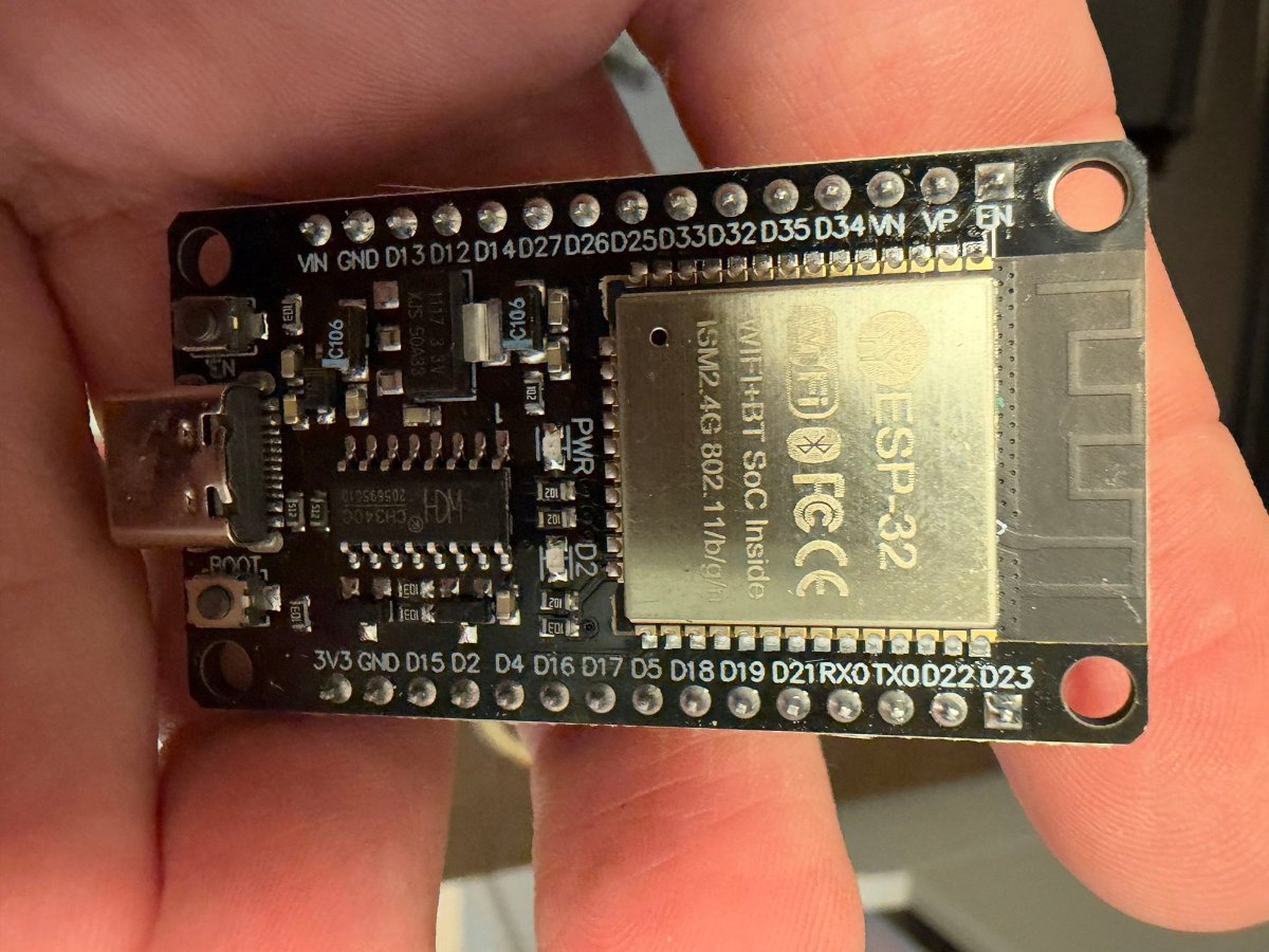
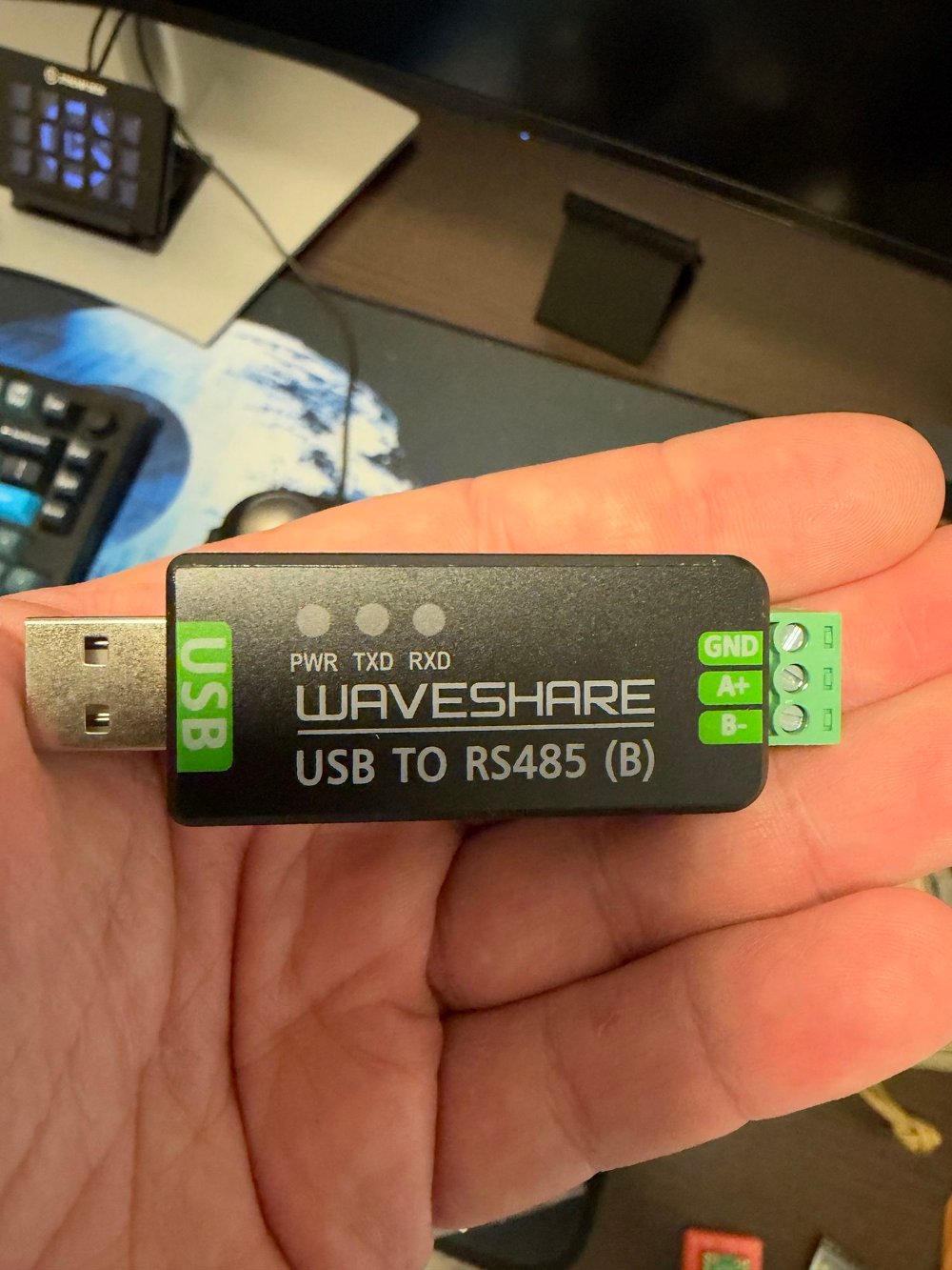
There was an ESP32, an RS-485 module, two Raspberry Pi Picos, an Elfin EW11A, and a Waveshare USB to RS-485 adapter. Claude picked the Waveshare for a first test without soldering: a network cable with one plug cut off, three wires into the adapter, the adapter into my laptop.
At 20:53 I wrote “plugged everything in. go ahead”. Claude logged into my laptop over SSH and started a small Python script to listen to the bus. The messages came in clean, with zero checksum errors. Then, with my OK, it sent one write into the gap after the broadcast: fan to 40 %.
The fan got quieter. The panel on the wall showed 40 %. The status message on the bus said 2E 28, which is 40. Then the same for 80 % to put it back. At 20:57 Claude wrote “MITM isn’t needed”. I was really happy at that point. Nothing to cut, nothing to solder, and the panel didn’t even notice us.
There was one small lesson in it. The first try to go back to 80 % was ignored: the script had answered an old broadcast still waiting in the laptop’s buffer, too late for the gap. The second try worked at once, so on this bus timing really matters.
Pressing every button
Before building anything permanent, I wanted to know the rest of the language:
I want you to sniff the commands and replies now to put together as much info about the protocol as possible. I’m going to the panel now to switch modes. then I’ll write you the sequence
Claude asked me to write down the time of each press. I said I wouldn’t. Claude said that was fine, it would match them by order. So I pressed, and afterwards I sent this:
100% 80% 60% 40% 20% 0% 20% T sun snow snow T T T T some number of times, top and bottom arrows together reset that the filter was changed 40% 60% 80%
That turned out to be enough, because every press showed up as a write from the panel, in the same order. The T button is register 31: 0 Manual, 1 Auto, 2 Boost, 3 Sleep, 4 Calendar. The snowflake (night cooling) is register 33. The sun did nothing, because my unit has no heater. Claude also had to correct itself here. In my old summer recordings it had called two registers “temperatures”, 22 and 18. On a November evening they still said 22 and 18, so they were set-points, not temperatures. The status message doesn’t contain any temperatures at all.
No soldering, please
Claude’s plan for the permanent part was the ESP32 with the RS-485 module. It said the Elfin, which goes over Wi-Fi, would be too slow to hit that short gap reliably. I didn’t want to solder:
I’d still rather use the elfin so I don’t have to solder anything. Especially since it has a cable
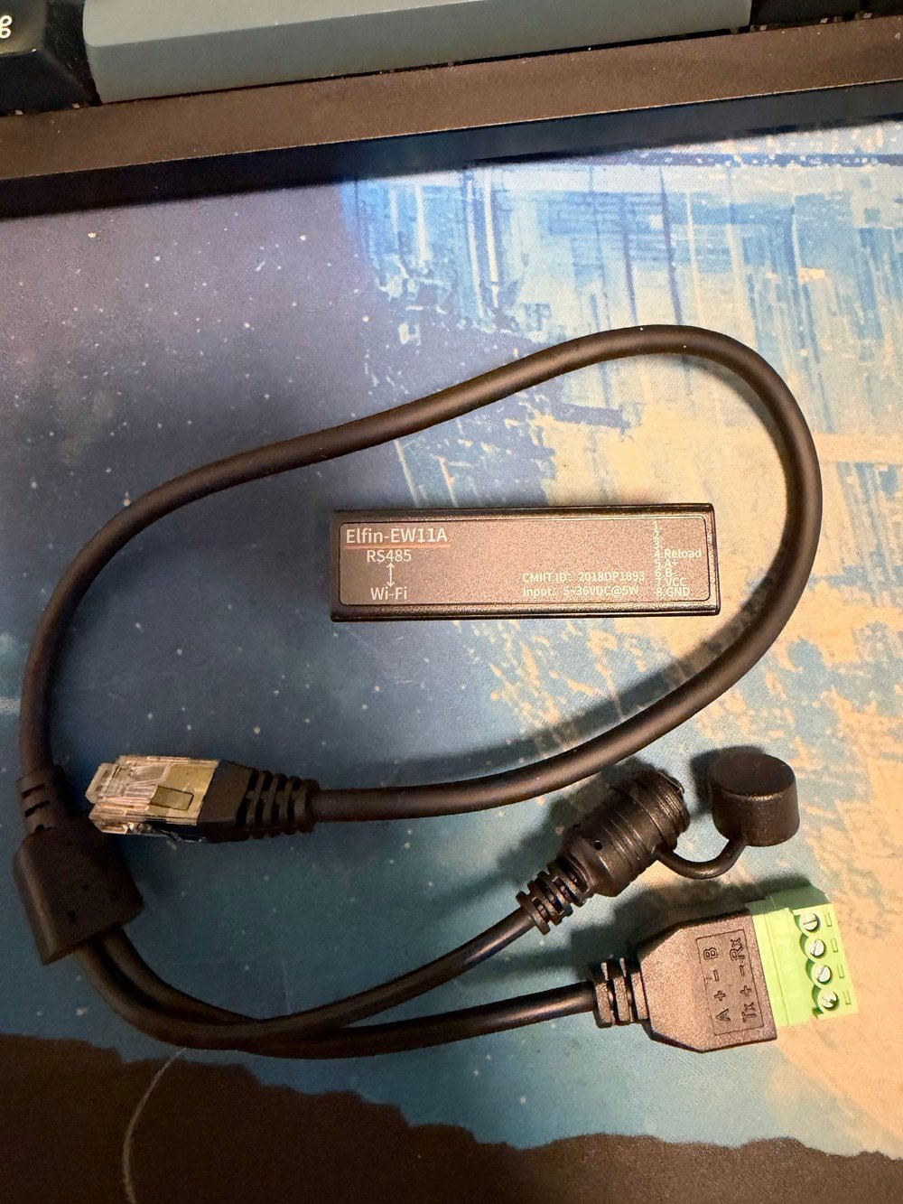
Claude agreed and wrote a small Python service to run in a container on my server: it would talk to the Elfin over TCP and to Home Assistant over MQTT. That was one more thing to look after, so I asked:
can we do it without an extra docker container? the elfin probably can do mqtt somehow?
It turned out it can: the Elfin has an MQTT mode: everything from the bus goes to one topic, everything from another topic goes onto the bus. So all the logic could live in Home Assistant itself. Claude wrote that in about seven minutes.
I worried that a message every hundred milliseconds would slow Home Assistant down. Claude counted about nine messages a second and estimated around 1 % of one CPU core. Most of them change nothing, and a sensor that doesn’t change doesn’t write to the database. It also suggested a setting on the Elfin that packs a burst of messages into one, which brings it down to about three a second.
Then I stood in front of the Elfin’s cable and didn’t get it:
I don’t quite understand which wire goes where
Its cable ends in a green block with four screws, marked A, +, − and B. Claude explained it as a table: blue (pin 4) to A, white-blue (pin 5) to B, nothing on “+”, because that’s the Elfin’s own power and it would go into the HRV. I set up the Elfin’s Wi-Fi and MQTT in its web page and plugged it in. I created the MQTT user myself, so the password never went through Claude.
The first command from Home Assistant
While I was at the Elfin, Claude put the Home Assistant part in place: two files, a config check, a reload, no restart. It tested the whole chain with fake messages before anything touched the real bus. One thing went wrong there. The first version used an old way of writing template entities, and Home Assistant showed me two repair warnings:
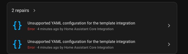
Claude had already rewritten that part in the new style, so it just dismissed the two warnings.
At 22:45 the Elfin logged into MQTT, and the real messages came in. The first command from Home Assistant: 60 %, confirmed on the fifth try, after about five seconds. Back to 80 %: second try. So the Elfin over Wi-Fi does miss the gap sometimes, but it never misses for long. Since then the logbook shows between two and eight tries per change, a few seconds each time, which for ventilation doesn’t matter at all. Claude’s worry about Wi-Fi was right in theory, and it didn’t matter in practice.
Later I unplugged and replugged the Elfin and asked “is it working now? I reconnected it”, and it was.
The last step on Sunday was mine too. Home Assistant showed about twenty loose entities and no device, and I couldn’t find the HRV in the device list:
Can we still make it a device and not entities? It’ll be more convenient
Template entities in Home Assistant can’t belong to a device, but MQTT entities can. So Claude added one more layer: the templates read the bus and publish clean values to MQTT, and an MQTT device called “House HRV” shows them. Commands from the device go back the other way. At 23:10 there was one device with a fan, the modes as presets, a night-cooling switch and a few status flags. Claude couldn’t delete the old dead ESP device, because that’s not something you can undo, so I clicked that one myself.
How the trick works
First the language itself. I’m writing it out in full, because if you have a ventilation unit, a heat pump or anything else with a wall panel on a network cable, there’s a good chance it talks something like this. And nobody had written this one down before.
The wires
The panel cable is a normal network cable (T568B). Only a few of its eight wires matter:
| Pin | Colour | What it is |
|---|---|---|
| 4 | blue | RS-485 A |
| 5 | white-blue | RS-485 B |
| 2, 3, 7, 8 | orange, white-green, white-brown, brown | ground |
| 6 | green | a 1 Hz square wave from the controller (not data, leave it alone) |
| 1 | white-orange | probably power for the panel; I measured nothing on it at socket 2 (don’t connect it) |
The serial settings are 9600 baud, 8 data bits, no parity, 1 stop bit (8N1). If you clip a logic analyzer to only one wire of the pair, the signal looks inverted. That’s the checkbox I was missing.
The messages
Every message is plain text: hex digits, then a carriage return. So you can read the bus in any serial terminal. The controller writes lower-case letters and the panel writes upper case, which helps when you’re reading a log.
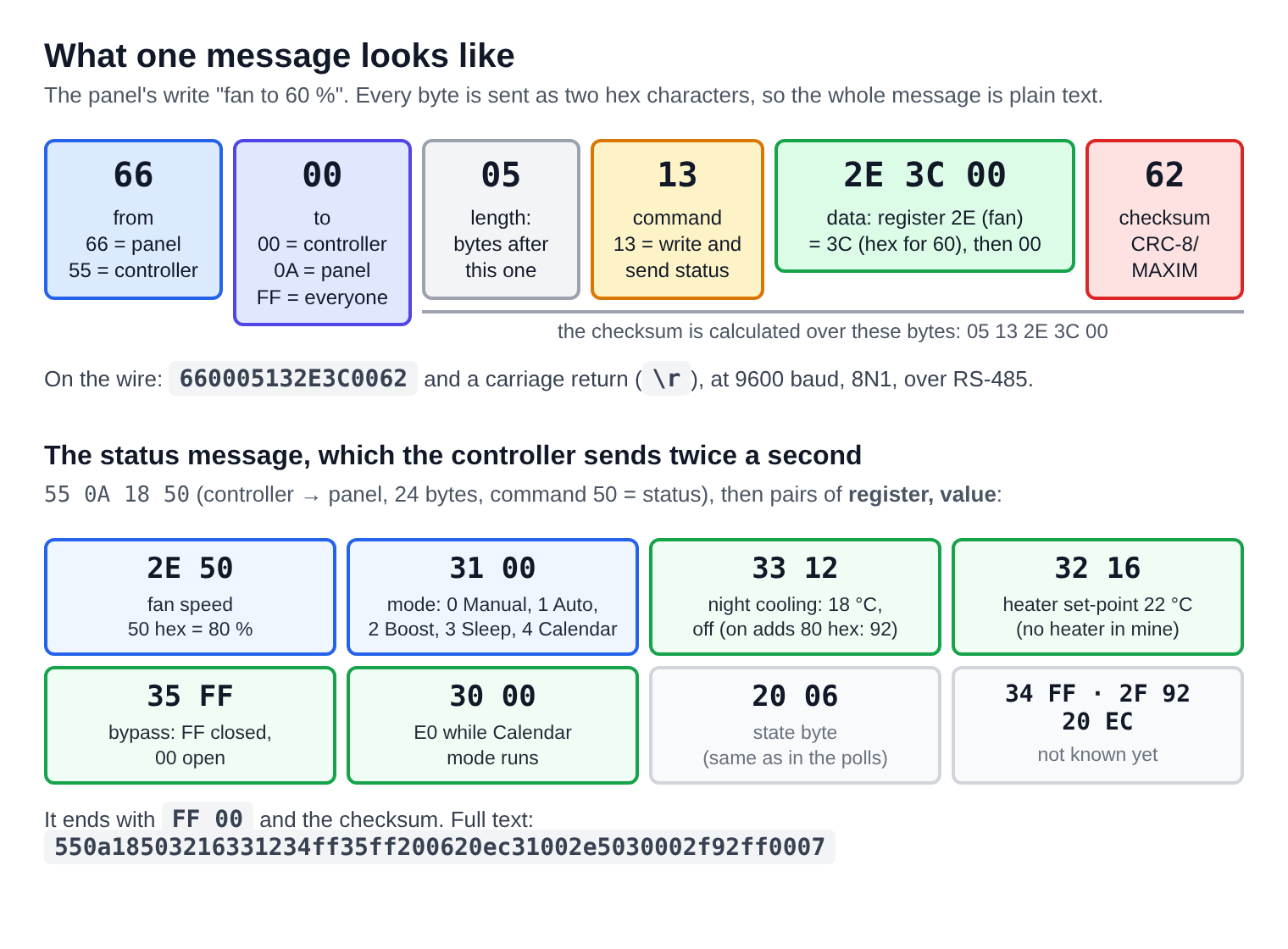
Each message has the same six parts:
- From.
55is the controller,66the panel. - To.
00is the controller,0Athe panel,FFeveryone. - Length. How many bytes come after this one, the checksum included.
- Command. What the message is (the table below).
- Data. Zero or more bytes.
- Checksum. CRC-8/MAXIM, the same one the Dallas 1-Wire temperature sensors use, calculated over the length, command and data (not over “from” and “to”).
These are all the commands I’ve seen:
| Command | Who sends it | What it means |
|---|---|---|
20 | controller | “your turn to speak”, with the controller’s state byte as data |
01 | panel | “nothing to say” |
11 | panel | “send me the status” |
03 | panel | “write this register”: register, value, 00 |
13 | panel | the same write, plus “and send me the status” |
10 | both | “OK, got it” |
50 | controller | the status: pairs of register and value, ending with FF 00 |
And the registers, which are the actual settings:
| Register | What it is | Values |
|---|---|---|
2E | fan speed, in % | 00 14 28 3C 50 64 = 0, 20, 40, 60, 80, 100 %; Home Assistant can write any value, Auto mode uses steps of 1 % |
31 | mode (the T button) | 00 Manual, 01 Auto, 02 Boost (15 min), 03 Sleep, 04 Calendar |
33 | night cooling (the snowflake) | the low 7 bits are the set-point in °C (12 = 18 °C); add 80 to switch it on (92) |
32 | heater (the sun) | the same layout as 33; does nothing on my unit, which has no heater |
35 | bypass | FF closed, 00 open |
30 | calendar | E0 while Calendar mode runs |
The state byte in the controller’s 20 messages has two useful bits: 02 means the bypass is open, and 08 means a timed mode (Boost or Sleep) is running.
Who talks when
The controller is in charge, and nobody else speaks unless it asks them to. About twice a second it asks the panel (55 0A 03 20 01 7B), and the panel answers 20 to 100 milliseconds later. Once a second it also sends a message to everyone (55 FF 03 20 06 F8) and asks the panel only 40 ms later. Nobody answers the message to everyone, so for about 27 ms the bus is silent. That gap is where Home Assistant talks.
Building a message yourself
This is enough to build and check messages in Python:
def crc8_maxim(data: bytes) -> int:
    crc = 0
    for b in data:
        crc ^= b
        for _ in range(8):
            crc = (crc >> 1) ^ 0x8C if crc & 1 else crc >> 1
    return crc

def frame(src, dst, cmd, data):
    body = bytes([len(data) + 2, cmd, *data])     # length counts command, data and checksum
    return (bytes([src, dst]) + body + bytes([crc8_maxim(body)])).hex().upper() + "\r"

def parse(line):
    b = bytes.fromhex(line.strip())
    ok = b[2] == len(b) - 3 and crc8_maxim(b[2:-1]) == b[-1]
    return {"from": b[0], "to": b[1], "cmd": b[3], "data": b[4:-1].hex(" "), "crc_ok": ok}

frame(0x66, 0x00, 0x13, [0x2E, 0x3C, 0x00])   # '660005132E3C0062\r': fan to 60 %
One write, step by step
So this is what happens when you move the slider in Home Assistant:
- You set 60 % in Home Assistant. A short template builds the message the panel would send:
66 00 05 13 2E 3C 00plus the checksum62. - It waits for the next broadcast from the controller,
55 FF 03 20 06 F8, which comes once a second. - It sends the message straight away, into the gap where nobody talks.
- The panel asks for the status anyway, twice a second. Home Assistant reads it too. If register
2Esays3C, the write is done. - If not, it sends the same message after the next broadcast, at most 15 times, and then it gives up and tells me.
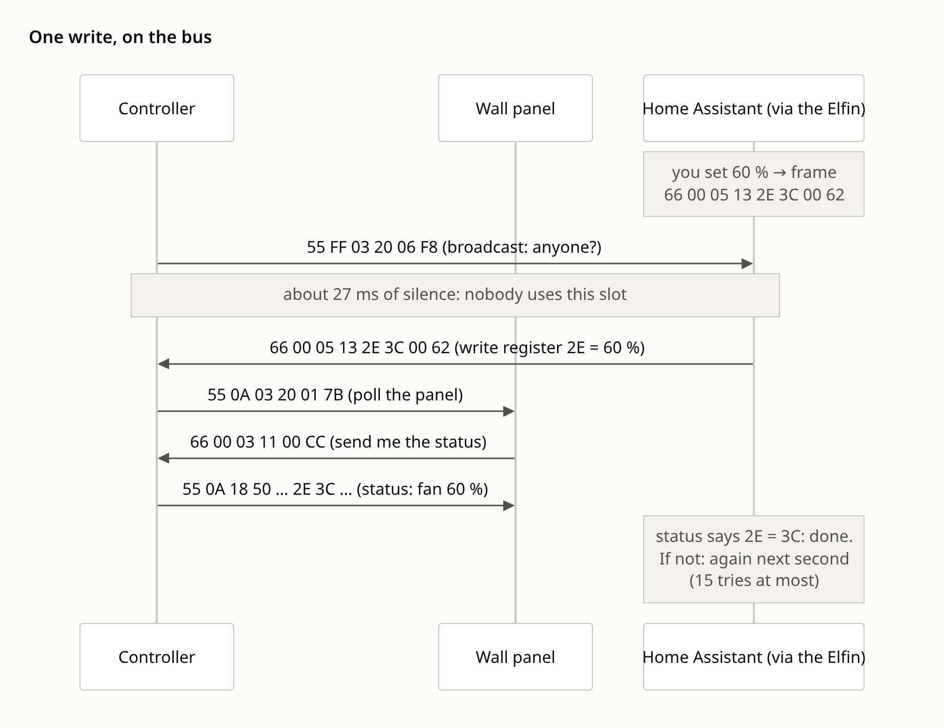
The panel doesn’t know any of this happened. It just asks for the status, sees 60 %, and shows 60 %.
The checksum is the only bit of real maths, and in Home Assistant it’s a lookup table in a Jinja macro:
{%- macro frame(reg, val) -%}
{%- set body = [5, 19, reg|int, val|int, 0] -%}
{%- set c = crc8(body)|int -%}
{{ '66000513%02X%02X00%02X' % (reg|int, val|int, c) }}
{%- endmacro -%}
The Home Assistant parts that do the writing (macros, script, two automations)
custom_templates/hrv.jinja:
{%- macro reg(frame, r) -%}
{%- set d = frame[8:-2] if frame is string and frame|length > 12 else '' -%}
{%- set ns = namespace(v='') -%}
{%- for i in range(0, (d|length) - 3, 4) -%}
  {%- if ns.v == '' and d[i:i+2]|lower == r|lower -%}{%- set ns.v = d[i+2:i+4]|lower -%}{%- endif -%}
{%- endfor -%}
{{ ns.v }}
{%- endmacro -%}

{%- macro crc8(bytes_list) -%}
{#- CRC-8/MAXIM lookup table, 256 values: see the Dallas/Maxim 1-Wire CRC; shortened here -#}
{%- set t = [0,94,188,226,97,63,221,131,194,156,126,32,163,253,31,65, ...] -%}
{%- set ns = namespace(c=0) -%}
{%- for b in bytes_list -%}{%- set ns.c = t[ns.c|bitwise_xor(b)] -%}{%- endfor -%}
{{ ns.c }}
{%- endmacro -%}

{%- macro frame(reg, val) -%}
{%- set body = [5, 19, reg|int, val|int, 0] -%}
{%- set c = crc8(body)|int -%}
{{ '66000513%02X%02X00%02X' % (reg|int, val|int, c) }}
{%- endmacro -%}
In the package (the Elfin publishes to hrv/rx and listens on hrv/tx; sensor.hrv_status_frame keeps the last status message from hrv/rx):
script:
  hrv_write:
    alias: "HRV: write a register on the panel bus"
    mode: queued
    fields:
      reg: { description: "46 = 0x2e fan %, 49 = 0x31 mode, 51 = 0x33 night cooling" }
      val: {}
    sequence:
      - action: input_text.set_value
        target: { entity_id: input_text.hrv_pending_frame }
        data:
          value: "{% from 'hrv.jinja' import frame %}{{ frame(reg, val) }}"
      - action: input_number.set_value
        target: { entity_id: input_number.hrv_write_attempts }
        data: { value: 0 }

automation:
  - id: hrv_bus_send_pending_write
    alias: "HRV bus: send the pending write after the broadcast poll"
    mode: single
    triggers:
      - trigger: mqtt
        topic: hrv/rx
    conditions:
      - "{{ '55ff0320' in (trigger.payload | string | lower) }}"
      - "{{ states('input_text.hrv_pending_frame') | length == 16 }}"
      - "{{ states('input_number.hrv_write_attempts') | int(0) < 15 }}"
    actions:
      - action: mqtt.publish
        data:
          topic: hrv/tx
          payload: "{{ states('input_text.hrv_pending_frame') }}\r"
      - action: input_number.increment
        target: { entity_id: input_number.hrv_write_attempts }

  - id: hrv_bus_confirm_write
    alias: "HRV bus: clear the pending write once the status shows it"
    mode: queued
    triggers:
      - trigger: state
        entity_id: sensor.hrv_status_frame
    conditions:
      - "{{ states('input_text.hrv_pending_frame') | length == 16 }}"
      - >-
        {% from 'hrv.jinja' import reg %}
        {% set p = states('input_text.hrv_pending_frame') | lower %}
        {{ reg(trigger.to_state.state, p[8:10]) == p[10:12] }}
    actions:
      - action: logbook.log
        data:
          name: HRV
          message: "write {{ states('input_text.hrv_pending_frame')[8:12] }} confirmed after {{ states('input_number.hrv_write_attempts') | int(0) }} attempt(s)"
      - action: input_text.set_value
        target: { entity_id: input_text.hrv_pending_frame }
        data: { value: "" }
These are only the parts that write. The full package also reads the speed, mode, set-points and status flags out of the status message, and builds the MQTT device.
Monday morning: let the air decide
On Monday at 07:09 I asked a new question:
As I have house Hrv/fan/recurperation control, propose quality of life improvements and energy usage reductions
Claude pulled a week of data from Home Assistant first, and it wasn’t flattering. The fan had run at 80 % around the clock, 99 W, all week. In the daytime every room sat at a comfortable 450 to 600 ppm of CO2, so 80 % was more than the house needed. But in the bedroom CO2 climbed to 1,500 or 1,600 ppm every night, even at 80 %. Claude said the bedroom was an airflow problem, not a speed problem: going from 80 % to 100 % adds only about a quarter more air. Check the vent and the door first.
Then it suggested measuring the real power at each speed, and I said yes. The fan went through every step for five minutes each, with the power read from the smart plug the HRV runs on:
| Fan | Power | kWh per day, if left there |
|---|---|---|
| 20 % | 9 W | 0.22 |
| 40 % | 17 W | 0.42 |
| 60 % | 41 W | 0.99 |
| 80 % | 99 W | 2.37 |
| 100 % | 187 W | 4.49 |
That’s a steep curve: 60 % costs less than half of 80 %. So Claude’s plan was: set the speed from the highest CO2 of the three rooms that have sensors (bedroom, living room, my home office), go down when nobody is home, and start the HRV’s own 15-minute Boost when someone takes a shower. Any press on the wall panel, or any change from the app, pauses the automation for two hours, so whatever you do by hand always wins. And a switch turns the whole thing off.
I changed two things before saying yes:
A few proposals to correct. Over 1000ppm 80%. Do not use mmWave sensors for room presence for that automation. They are not fully configured yet.
So the steps are: under 650 ppm 40 %, 650 to 1,000 ppm 60 %, over 1,000 ppm 80 %. It steps up at once, and it steps down only 75 ppm below the line and at least 15 minutes after its last change, so it doesn’t flap. “Away” is 20 % after 30 minutes with nobody home, as long as CO2 is low. 100 % is only for the shower boost.
At 08:27 on Monday the automation was on. Seven minutes later it made its first decision on its own: “80 → 60 % (highest CO2 900 ppm)”. The chart at the top shows how the next day and a half went.
Claude as JARVIS: what went well and what didn’t
What Claude did well
- It found the one missing checkbox in recordings I had given up on, and decoded the whole protocol from them in seven minutes, checksum included.
- It turned my question about the second socket into a test the same evening, and noticed the gap in the conversation that made it possible.
- It ran the first test on my laptop over SSH and waited for my OK before it sent anything to the HRV.
- It checked everything it could without touching the house: fake messages through MQTT, a config check before every reload, no restart.
- It looked at a week of data before suggesting any automation, and measured the power curve instead of guessing it.
What it got wrong
- The wiring. A whole afternoon of designs for a single 5-volt wire, on a bus that was RS-485 all along. My multimeter fixed that, not Claude.
- Two registers called “temperatures” that were set-points.
- “The Elfin over Wi-Fi will be too slow.” It works fine.
- It wrote and compiled ESP32 firmware, twice, that we never flashed.
- It didn’t see my commit with the pin mapping until I said “check again”.
- The energy saving: first guessed too low, then planned too high.
What only I could do
- Make the recordings in the first place, and measure the pins with a multimeter.
- Ask “what about socket 2?”
- Say no to soldering, and no to one more container to look after.
- Want a device instead of loose entities.
- Know that the mmWave presence sensors aren’t ready, and that 80 % should start at 1,000 ppm.
The small annoying things. My laptop fell asleep in the middle of a test, so one experiment never happened (it turned out not to matter). Claude isn’t allowed to delete the old dead device, so I had to click it myself. And it took me a while to understand which wire goes into which screw of the Elfin.
So no, it isn’t the JARVIS from the films. It got the wiring wrong for hours, and it needed my multimeter and my hands. But on Sunday at lunchtime I had a dead app and a PDF in Polish. On Monday morning the house was choosing its own fan speed. And the day before, the same JARVIS had put a camera on my water meter, so it was quite a weekend.
If you want to build one
What you need
- A way to listen to the bus: a USB to RS-485 adapter for a laptop is the cheapest and quickest. A cheap logic analyzer helps if you don’t know yet what’s on the wires.
- An RS-485 to Wi-Fi adapter with an MQTT mode, like the Elfin EW11A. Or an ESP32 with an RS-485 module, if you don’t mind soldering.
- Home Assistant with an MQTT broker (I use the Mosquitto add-on).
What carries over. If you have a Smartvent HRV with the Smart Control board and a Smarttouch panel, the protocol above should be the same. You can probably copy the whole thing. Other brands will speak something else, but the way to find out is the same: record the panel cable, press one button at a time, and look for the checksum.
The settings that worked for me
| Thing | Setting |
|---|---|
| Bus | RS-485, 9600 baud, 8N1; A on pin 4 (blue), B on pin 5 (white-blue) of the second socket |
| Elfin serial | 9600 8N1, protocol “None” (not Modbus: this bus isn’t Modbus) |
| Elfin network | MQTT client, publishes to hrv/rx, subscribes to hrv/tx |
| Elfin gap time | about 20 ms, so a burst of messages arrives as one |
| Write | right after the broadcast 55 FF 03 20 xx, repeated until the status confirms it, at most 15 times |
| CO2 steps | under 650 → 40 %, 650–1,000 → 60 %, over 1,000 → 80 % |
| Away | 20 % after 30 minutes with nobody home |
| Shower | the HRV’s own 15-minute Boost on a humidity jump |
What I would tell myself before starting
- Before building anything, I’d look for a free socket first, because the device that’s gone may have left a way in.
- I’d measure every pin against a real ground, since two wires that look like “signal and ground” may really be a pair.
- When a decoder shows garbage, I’d try “invert” before anything else.
- I’d record while pressing each button once, slowly, because ten minutes of that gave us the whole register map.
- I wouldn’t believe “too slow over Wi-Fi” until I’d tried it, because a retry and a look at the next status fix a lot.
- I’d measure the power curve before counting the savings, and then count them again with real data.
- And I’d fix the airflow to a room before automating the fan, because a faster fan doesn’t help a room the air doesn’t reach.
What’s next
- Fix the bedroom air: the vent and the door.
- An alert when the bus goes silent.
- A tile on the wall iPad and voice commands (“air the house”, “ventilation to minimum”).
- A smog guard: in winter the wood smoke outside peaks at night. A better intake filter first, then maybe a lower speed when the air outside is bad.
- Find the rest of the language. The status message has no temperatures, humidity or errors, but the old Wi-Fi module must have read them somehow.
- Fireplace mode: the panel has one, and I haven’t recorded it yet.
Versions
| Thing | Version |
|---|---|
| HRV | Smartvent Ecobox, controller board Smart Control v1.62, Smarttouch wall panel |
| Bus | RS-485, 9600 8N1, ASCII hex messages, CRC-8/MAXIM |
| Wi-Fi bridge | Elfin EW11A in MQTT mode, on the controller’s PANEL2 socket |
| First test | Waveshare USB to RS-485 (B) on a laptop with openSUSE Tumbleweed, a Python script |
| Recording | 24 MHz 8-channel logic analyzer (Saleae clone), sigrok / PulseView |
| Home Assistant | 2026.10.2 on Home Assistant OS 18.3, Mosquitto add-on |
| CO2 sensors | Everything Presence Lite in the bedroom, living room and home office |
| Power | measured with the Shelly smart plug the HRV runs on |
| Never used | ESP32 firmware for a man-in-the-middle box and for socket 2 (ESPHome 2026.10.2, compiled, not flashed) |
| Assistant | Claude in Claude Code, two sessions |
How this post was written: Claude drafted it from the transcripts of our sessions, the project notes and Home Assistant’s own history, and drew the diagrams and the chart. The prompts and Claude’s answers are quoted from those transcripts.
Comments
Comments are GitHub Discussions; you need a GitHub account to write one.